Battery switch on travel trailer function is crucial for managing your RV’s power. Understanding how your battery switch works is key to avoiding dead batteries and electrical issues on the road. This guide will walk you through the different types of switches, their operation, troubleshooting, safety, and even upgrades. We’ll cover everything from basic functionality to advanced wiring diagrams, ensuring you’re confident in managing your travel trailer’s power system.
We’ll explore various battery switch types, including rotary, push-button, and electronic options, comparing their pros and cons. We’ll then delve into the step-by-step operation of a typical switch, illustrating power flow with diagrams and flowcharts. Troubleshooting common problems like no power or intermittent power will be covered with easy-to-follow steps. Finally, we’ll discuss important safety precautions and maintenance tips to keep your system running smoothly.
Battery Switch Functionality and Operation
Understanding your travel trailer’s battery switch is crucial for managing power and preventing accidental drain. This switch controls the flow of electricity from your batteries to the trailer’s systems, allowing you to selectively use one battery, both batteries, or disconnect them entirely. Proper operation ensures optimal battery life and prevents damage to your electrical system.
A typical battery switch in a travel trailer is a multi-position rotary switch. It usually has three or four positions, allowing you to select which battery (or batteries) power your trailer’s systems. The positions typically include “Off,” “Battery 1,” “Battery 2,” and sometimes “Both.” Before operating the switch, always make sure you understand the labeling and position of each setting.
Battery Switch Operation Steps
Operating the battery switch is straightforward. Locate the switch, usually near your battery bank. The switch itself will have clearly marked positions. Carefully rotate the switch to the desired position, ensuring it clicks firmly into place. Listen for a distinct click to confirm the switch is fully engaged.
Avoid forcing the switch.
Internal Workings of a Common Battery Switch
A diagram of a typical three-position battery switch (Off, Battery 1, Battery 2) would show three main terminals: one for the positive (+) input from the batteries, one for the positive (+) output to the trailer’s electrical system, and one for the negative (-) output. Internally, the switch uses a rotating selector to connect the input to the appropriate output based on the selected position.
In the “Off” position, the input is disconnected from the output, preventing power flow. In “Battery 1,” the input is connected to the output through the path for Battery 1. In “Battery 2,” the connection shifts to the path for Battery 2. A more complex four-position switch (adding “Both”) would include internal circuitry to connect both battery paths to the output simultaneously.
Imagine a simple diagram: a circle representing the rotary switch with three positions (Off, Battery 1, Battery 2) marked around its circumference. Three lines radiate from the center of the circle: one labeled “Battery 1 (+)”, one labeled “Battery 2 (+)”, and one labeled “Trailer (+)”. The rotary switch’s internal mechanism moves a contact point within the circle, connecting the “Trailer (+)” line to either “Battery 1 (+)”, “Battery 2 (+)”, or disconnecting it entirely in the “Off” position.
A similar arrangement exists for the negative terminals, although it’s often simpler due to the nature of the negative connection.
Power Flow Through the Battery Switch
A flowchart visually represents the power flow through the switch in various positions. This helps visualize how the switch directs the power.
The flowchart would start with a box labeled “Battery 1” and another labeled “Battery 2”. Arrows would lead from each battery to a central decision point represented by the battery switch. From the switch, arrows would lead to a final box labeled “Trailer Electrical System”. Each position of the switch would determine which path the arrow takes. For example:
- Off: No arrows lead to the “Trailer Electrical System” indicating no power flow.
- Battery 1: An arrow would connect “Battery 1” directly to “Trailer Electrical System”, while “Battery 2” is isolated.
- Battery 2: An arrow would connect “Battery 2” directly to “Trailer Electrical System”, while “Battery 1” is isolated.
- Both: Arrows would connect both “Battery 1” and “Battery 2” to the “Trailer Electrical System”, showing combined power flow.
Troubleshooting Common Battery Switch Issues
Dealing with a malfunctioning battery switch in your travel trailer can be frustrating, especially when you’re on the road. Understanding the common problems and how to diagnose them can save you time and potential headaches. This section Artikels the most frequent issues and provides a step-by-step guide to resolving them.
So, you’re an audiophile who travels? Awesome! Check out this guide on audiophile travel setups for tips on packing your precious gear. It’s all about finding that sweet spot between portability and sound quality. Then, once you’ve got your portable setup dialed in, head over to audiophile travel aetup for some inspiration on enjoying your music on the go.
They’ve got great suggestions for finding the perfect listening environment wherever your travels take you. Happy listening!
Battery Switch Showing No Power
This is a classic problem. No power from the battery switch means your house batteries aren’t supplying power to your trailer’s 12-volt system. This could be due to several factors, ranging from a simple blown fuse to a more serious problem with the switch itself.
The most likely culprits are a blown fuse in the battery switch circuit, a faulty switch, or a disconnected wire. Check these first before considering more complex issues.
Here’s a systematic approach to diagnosing the problem:
- Check the fuses: Locate the fuse box for your battery switch circuit and inspect the fuses for any that are blown (usually indicated by a broken filament). Replace any blown fuses with fuses of the same amperage rating.
- Inspect the battery switch: Carefully examine the switch itself for any signs of damage, corrosion, or loose connections. Tighten any loose connections and clean any corrosion using a wire brush and contact cleaner.
- Test the battery connections: Verify that the battery cables are securely connected to both the battery terminals and the battery switch. Loose or corroded connections can significantly impede power flow.
- Test the switch itself: If the previous steps don’t solve the issue, use a multimeter to test the continuity of the switch. If the switch is faulty, it will need to be replaced.
- Trace the wiring: If all else fails, carefully trace the wiring from the battery switch to the loads in your trailer. Look for any broken or damaged wires that may need repair or replacement.
Intermittent Power from the Battery Switch
An intermittent power supply suggests a problem with a connection or a component that’s failing sporadically. This could be due to loose connections, corrosion, or a failing part within the switch itself.
Intermittent power is often caused by loose or corroded connections. Thoroughly check all connections and clean any corrosion.
Here’s how to tackle this issue:
- Inspect all connections: Carefully examine all connections related to the battery switch, including those at the battery terminals, the switch itself, and any wiring leading to your trailer’s 12-volt system. Pay close attention to any areas that show signs of corrosion or looseness.
- Check for loose wires: Wiggle the wires gently while testing the switch. If the power flickers, you’ve likely found a loose connection that needs tightening or repair.
- Look for corrosion: Corrosion can create an intermittent connection. Clean any corroded areas with a wire brush and contact cleaner. Apply dielectric grease to prevent future corrosion.
- Consider a failing switch: If the problem persists, the battery switch itself might be failing. Replacing the switch is the likely solution in this case.
Battery Switch Overheating
A hot battery switch is a serious issue that indicates a high current draw or a short circuit. This situation needs immediate attention to prevent damage to the switch and potential fire hazards.
Overheating indicates a significant problem. Immediately disconnect the battery switch to prevent further damage.
Here’s what to do:
- Disconnect the battery switch immediately: Turn off the switch and disconnect the battery cables to prevent further damage or fire hazards.
- Check for short circuits: Carefully inspect all wiring connected to the battery switch for any signs of short circuits, such as frayed wires or wires touching metal parts.
- Check amperage draw: Use a clamp meter to measure the current draw on the battery switch circuit. A significantly high amperage draw indicates a problem that needs to be addressed.
- Inspect all loads: Check all 12-volt devices connected to the battery switch. A faulty device drawing excessive current could be causing the overheating.
- Replace the switch: If a short circuit or excessive current draw is found, replacing the battery switch is recommended.
Safety Precautions and Maintenance
Working with RV batteries and their switching systems requires careful attention to safety. Improper handling can lead to serious injury from electric shock, burns, or explosions due to the release of flammable gases. Regular maintenance is crucial to ensure the longevity and reliable operation of your battery system.Proper safety measures are paramount when working with your RV’s battery system.
Always wear appropriate safety glasses and gloves to protect against acid splashes and potential short circuits. Ensure the area is well-ventilated to prevent the buildup of flammable hydrogen gas, a byproduct of battery operation. Never work on batteries near open flames or sparks. Before disconnecting or connecting any battery cables, always turn off the battery switch to completely isolate the power source.
Battery Switch Maintenance Procedures
Regular inspection and cleaning of your battery switch are essential for its long-term performance and safety. This includes visually inspecting the switch for any signs of corrosion, loose connections, or damage to the casing. A buildup of corrosion can impede the flow of electricity and lead to overheating or even fire. Cleaning can be achieved with a wire brush and baking soda solution to neutralize any acid spills.
After cleaning, apply a corrosion inhibitor to prevent future corrosion. It’s also important to check the tightness of all terminal connections. Loose connections can create resistance and generate heat, leading to potential failure. Regularly checking the switch’s operation ensures its smooth functioning and timely identification of any issues.
Connecting and Disconnecting Batteries
A visual representation of the correct procedure would show the following steps: First, ensure the battery switch is in the “OFF” position. Next, disconnect the negative (-) cable from the battery terminal first using a wrench, taking care not to short the cable against any metal parts. Then, disconnect the positive (+) cable. When reconnecting, reverse the process: connect the positive (+) cable first, followed by the negative (-) cable.
This ensures that you don’t accidentally create a short circuit during the process. Always double-check that the connections are secure and that no cables are touching each other or any metal parts of the RV. The image would also highlight the importance of wearing safety glasses and gloves throughout the process.
Wiring Diagrams and Schematics
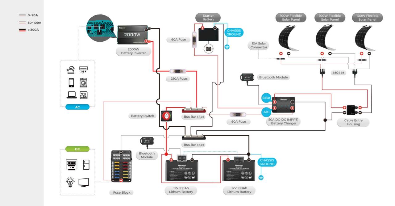
Understanding RV wiring diagrams is crucial for safely working with your battery switch. These diagrams visually represent the electrical pathways in your travel trailer, showing how different components connect and interact. Learning to interpret them allows for easier troubleshooting and prevents accidental damage.RV battery switch wiring diagrams typically use standardized symbols to represent components like batteries, switches, fuses, and loads (lights, appliances).
Lines represent wires, and their thickness often indicates wire gauge. Color-coding helps identify different circuits. The diagrams show the flow of electricity, illustrating how the battery switch controls power to various systems.
So, you’re an audiophile who travels? Awesome! Check out this guide on creating the perfect audiophile travel setup for amazing sound on the go. It covers everything from portable DACs to noise-canceling headphones. But what if you want something a bit more luxurious? Then you’ll definitely want to explore this other resource for high-end portable audio: audiophile travel aetup.
This site focuses on premium components and how to integrate them for a truly immersive listening experience, even when you’re miles from home. Remember, good sound doesn’t have to stay home!
Interpreting Common RV Wiring Diagrams
RV wiring diagrams utilize symbols to represent various components. A battery is usually shown as a pair of parallel lines (+ and – terminals). The battery switch is depicted as a switch symbol with connections to the battery and the load circuits. Fuses appear as a circle with a zig-zag line inside, indicating a break in the circuit in case of an overload.
Loads, such as lights or appliances, are represented by a simple load symbol or the specific appliance’s representation. Wire thickness on a diagram generally corresponds to wire gauge, with thicker lines representing heavier gauge wires capable of carrying more current. The diagram’s labels and annotations will provide essential information on voltage, amperage, and circuit functions.
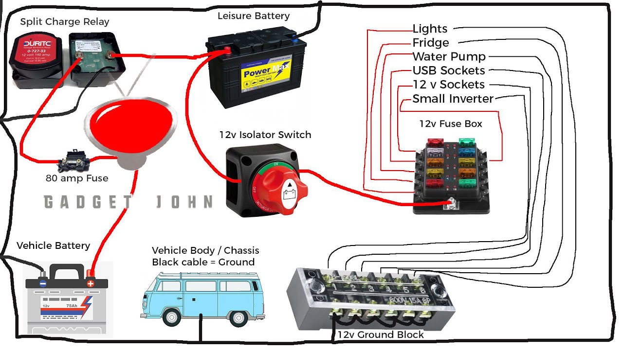
Examples of Different Wiring Configurations
Several common configurations exist for battery switches in RVs. A simple configuration might show a single battery connected to a switch, which then distributes power to the trailer’s 12V system. A more complex setup could involve two batteries (house and chassis), each connected to the switch independently, allowing for separate control over each battery bank. Another scenario could involve a battery switch controlling power to multiple circuits, with fuses protecting individual circuits from overloads.
Each configuration has implications for power management and safety. A single battery setup is simpler but offers less redundancy. Dual battery setups provide backup power and extend run-time.
Simplified Wiring Diagram Examples
Understanding different wiring setups is best illustrated with examples. Below are simplified wiring diagrams represented in tabular format. Remember, these are simplified examples and actual RV wiring may be more complex. Always refer to your specific RV’s wiring diagram before undertaking any electrical work.
| Component | Wire Gauge | Wire Color | Connection Point |
|---|---|---|---|
| Battery (12V) | 8 AWG | Red | Battery Positive (+) Terminal |
| Battery Switch | N/A | N/A | Input: Battery Positive (+), Output: Load Circuits |
| Fuse (30A) | 10 AWG | Red | Between Battery Switch and Load Circuit |
| Lights Circuit | 14 AWG | Red | Output of Fuse |
| Component | Wire Gauge | Wire Color | Connection Point |
|---|---|---|---|
| House Battery (12V) | 8 AWG | Red | Battery Positive (+) Terminal |
| Chassis Battery (12V) | 8 AWG | Red | Battery Positive (+) Terminal |
| Battery Switch (Dual Battery) | N/A | N/A | Input: House Battery (+), Input: Chassis Battery (+), Output: Load Circuits |
| Fuse (40A) | 8 AWG | Red | Between Battery Switch and Load Circuit |
| Water Pump Circuit | 12 AWG | Red | Output of Fuse |
Battery Switch Upgrades and Replacements
Upgrading or replacing your travel trailer’s battery switch can significantly improve your RV’s electrical system reliability and convenience. A faulty switch can lead to frustrating power issues, while an upgraded system offers features like improved isolation and easier management of multiple battery banks. This section details the process of replacing a faulty switch and upgrading to a more advanced system.Replacing a faulty battery switch is a relatively straightforward process, but always disconnect the battery’s negative terminal before starting any work to prevent electrical shocks.
Proper safety precautions are crucial throughout the entire process.
Replacing a Faulty Battery Switch
Replacing a faulty battery switch involves disconnecting the wiring from the old switch, carefully removing the old switch, and then installing the new switch, ensuring all connections are secure and correctly wired. This typically involves using appropriate tools like screwdrivers and wire strippers. Always consult your specific switch’s installation instructions. If you’re uncomfortable with electrical work, it’s best to consult a qualified RV technician.
Improper installation could damage your electrical system or create a fire hazard.
Comparing Battery Switch Brands and Models
Several reputable brands offer battery switches for travel trailers, each with varying features and price points. Popular choices include Blue Sea Systems, Perko, and AGS. Blue Sea Systems, for instance, is known for its robust construction and user-friendly designs, often featuring clear labeling and easy-to-use switches. Perko switches are also well-regarded for their durability, while AGS offers more sophisticated systems with features like remote control capabilities.
The best choice depends on your specific needs and budget. Consider factors like the number of battery banks you need to manage, the amperage rating required, and desired features such as remote control or digital displays.
Upgrading to a More Advanced Battery Switch System, Battery switch on travel trailer function
Upgrading to a more advanced system might involve switching from a simple two-battery switch to a more complex system that manages multiple batteries and allows for more precise control over power distribution. This could include incorporating a battery combiner or a sophisticated battery management system (BMS). A step-by-step guide for such an upgrade would depend heavily on the specific system chosen.
However, the general process includes planning the new wiring layout, acquiring the necessary components (switch, wiring, connectors, etc.), disconnecting the existing system, installing the new components according to the manufacturer’s instructions, and finally, testing the system thoroughly to ensure proper functionality and safety. Remember, careful planning and adherence to safety precautions are essential throughout this process. Always consult a professional if you are not comfortable performing this type of electrical work.
Mastering your travel trailer’s battery switch is essential for a smooth and enjoyable RV experience. By understanding the different types of switches, their operation, and potential troubleshooting steps, you can confidently manage your power and avoid frustrating breakdowns. Remember to prioritize safety and perform regular maintenance to keep your system running efficiently for years to come. With the knowledge gained here, you’ll be ready to hit the road with peace of mind, knowing you can handle any power-related situation that arises.
FAQs: Battery Switch On Travel Trailer Function
What happens if I accidentally leave my battery switch in the “off” position?
Leaving the switch off will disconnect your batteries from the trailer’s electrical system, preventing power to appliances and lights. You’ll need to turn the switch back on to restore power.
How often should I check my battery switch?
Visually inspect your battery switch monthly for any signs of corrosion, loose connections, or damage. Tighten any loose connections and clean any corrosion as needed.
Can I use a different type of battery switch as a replacement?
While you can replace a switch, ensure the replacement has the same amperage rating and is compatible with your existing wiring. Consult a qualified electrician if unsure.
Why is my battery switch getting hot?
A hot switch often indicates a loose connection or a high current draw. Inspect for loose wires and check for any short circuits in your system. A qualified electrician should address this issue.
